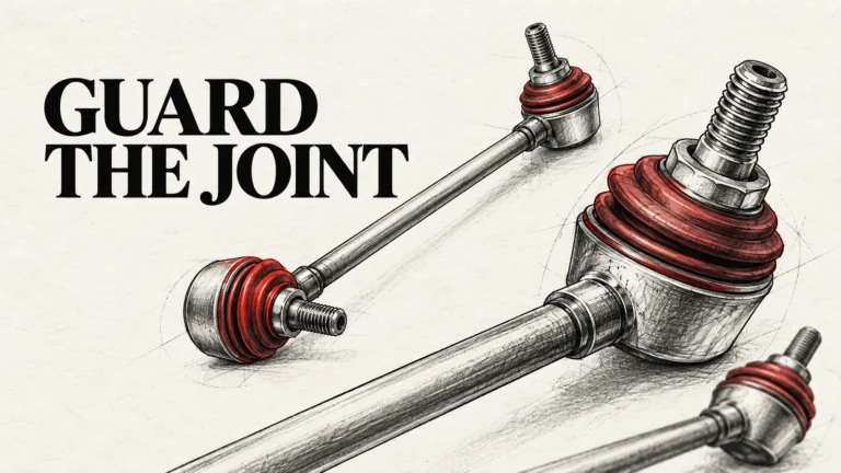

This guide gives purchasing teams a practical inspection sequence for a sample or supplier quotation. It does not assign a universal dimension or fitment to MAKEXCAR’s catalog. The correct specification belongs to the individual part and application. A visually similar link may still place a joint at the wrong angle or use the wrong stud, nut, or mounting arrangement.
Start with the vehicle and part identity
Record make, model, production period, relevant chassis or suspension variant, front or rear axle, and installation side before comparing measurements. Include the OE reference or the existing part number when it is reliable. Some catalogs separate left and right links; others list one symmetric part. Do not assume either pattern from a product photo. Confirm whether the quotation describes a single link, a pair, or a kit with nuts, washers, bushes, or sleeves.
If the vehicle has a modified ride height or nonstandard suspension, describe it. A catalog match for the original configuration may not settle the application question after a change. Ask the engineering or installation team to identify the mounting points and required clearance. Procurement can then ask suppliers to document that specific arrangement rather than inviting a broad “fits many models” answer.
Keep traceability tight: one drawing revision and one sample ID per comparison. A supplier may show a picture from a related family, while the actual quote is for a different revision. Capture photographs of both ends, the profile view, the label and package, plus the OE reference printed on the purchase request. These simple records prevent a correct measurement from being attached to the wrong part.
Measure center-to-center, not just overall length
For many ball-joint style links, the useful span is the distance between the centers of the two joints or studs. A ruler laid from one outermost tip to the other includes threaded projection and body-end details; it may give the same total on parts with different joint-center spacing. A drawing should name its datum points. If a seller says “length,” ask whether it means joint-center distance, body length, end-to-end dimension, or bolt length.
Measure a sample in a repeatable neutral position and note whether the joints can articulate. A bent or angled design may not yield a meaningful value from one flat photograph. Request a dimensioned drawing or a measured sample with a clear front and side view. Do not force a flexible joint into a position solely to obtain a preferred number. Record the tool, units, and reference points on the buyer comparison sheet.
Even an exact center-to-center match does not finish the fit check. The connecting rod may have a different offset or diameter, and the housings may interfere with the strut, control arm, anti-roll bar or wheel at suspension travel. Ask for the envelope and installation clearance where the application is tight. The article image below marks conceptual measurement locations; it supplies no part dimensions.

Check each stud and mounting interface
Record stud thread diameter and pitch, usable threaded length, shoulder dimensions if present, wrench or counterhold feature, and whether the nut is part of the supply. A nut that starts by hand is not proof that the pitch, locking design, or required engagement is correct. Mevotech’s product listings, for example, publish bolt thread size, bolt length, end type, included hardware, and application notes as distinct fields. They are examples of useful catalog fields, not MAKEXCAR specifications.
Also compare how each end attaches. One product may have ball studs at both ends; another may use a bushing, bolt or sleeve at one end. A catalog entry that describes the same overall span can therefore require different mounting hardware. Check hole diameter, stud seating form, nut type, washer order and boot clearance against the application documentation. Do not substitute hardware based solely on visual similarity.
When a sample arrives, compare both ends separately. Mark “end A” and “end B” on the inspection record rather than collapsing them into “same both ends.” Note whether the threads and wrench flats can be accessed in the vehicle. If installation instructions specify a counterhold or torque method, follow the vehicle and product-specific instructions. This guide intentionally gives no torque value because that value depends on the exact assembly.
Stud angle, offset and handedness can decide the fit
The studs may point in the same direction, oppose each other, or be rotated around the link body. A link that looks symmetric at a glance may be left- or right-handed. MOOG documents application examples in which angle-shifted ball pins distinguish left from right; its technical bulletin warns that reversed positioning can appear installable without unusual force. That is a reason to check the actual orientation, not a claim that every link is handed or that its example angle applies elsewhere.
Compare the candidate in the same view as the approved part. Put the foreground stud toward the camera and note where the far stud points; then rotate to a side view and check body offset. If a product has an arrow, color mark or side label, record what that mark means in its own documentation. Do not transfer a mark convention from another brand or vehicle.
The assembly should be checked at the intended mounting position with the suspension in the condition specified by the manufacturer. Clearance through the expected movement matters, not only clearance in a photograph with the wheels hanging. Where a link is installed on the wrong side, a ball joint may operate at an unfavorable angle. Review fit and movement before tightening rather than treating the ability to thread on a nut as acceptance.

Build a supplier comparison that exposes missing data
Use one row per feature and write the reference source next to each value. A drawing, measured sample, catalog statement and installer observation are different evidence types. If the source lacks a value, state “not supplied.” Do not back-calculate stud angle from a perspective product photograph or infer thread pitch from a nut that looks familiar.
| Fit question | Evidence to compare | Common shortcut to avoid |
|---|---|---|
| Is the application exact? | Vehicle, axle, side, OE reference and suspension variant | Matching only make and model |
| Is the span defined? | Joint center-to-center distance and measurement datum | Using unlabeled overall length |
| Do the ends mount? | Stud thread, end type, seating, nut and hardware scope | Assuming all threaded ends match |
| Is orientation correct? | Front/side views, stud angle, offset and handedness | Judging from one face-on photo |
| Does it clear? | Installed envelope and movement check for the application | Checking only static bench appearance |
It is useful to distinguish a quotation review from sample approval. A document set can eliminate obviously unsuitable candidates, but physical approval should use a representative part. Verify the received sample label and revision, measure the agreed dimensions, and record installation findings. A sample that differs from the drawing needs a supplier clarification before a bulk order.
What to do when measurements disagree
First, confirm that the same dimension is being compared. If one value is center-to-center and the other is tip-to-tip, the apparent mismatch may be a definition problem. Next, check units and drawing revision. Then confirm the sample identity and measurement setup. Photograph both parts side by side with datum points marked. This gives the supplier a precise question to answer.
Do not “correct” a mismatch by forcing the joint into position or changing hardware without engineering approval. A link may be close enough to begin assembly and still bind or lose clearance during travel. If the variation is intentional, request the application-specific explanation, revised drawing, and approval record. If it is a production deviation, keep the nonconforming sample separate from accepted inventory.
If the dispute concerns a returned link, collect the installed side, vehicle details, mileage or service time, mounting photos, supplied hardware, and any noise or interference conditions. These records help distinguish wrong application, orientation, installation and product issues. A photograph of a disconnected link alone rarely establishes why the problem occurred.
Frequently asked buyer questions
Can two links with the same overall length be substituted?
Not on that evidence alone. The joint-center span, end mounting, thread, stud orientation, handedness and clearance may differ. Confirm the exact OE or application reference and review a drawing or sample before treating them as alternatives.
Is center-to-center length always the published catalog length?
No. Catalogs may use different length conventions. Ask the supplier to identify the datum points and units for every quoted dimension. Keep the annotated drawing with the purchase record so later inspectors can repeat the check.
What if the link looks symmetrical?
Check both ends and their angular relationship anyway. MOOG’s handed link examples show why appearance alone can mislead. The correct orientation rule must come from the specific part documentation and vehicle application, not from a generic photo.
Send a fit-check request that can be answered
When reviewing MAKEXCAR stabilizer links, send the vehicle and suspension details, OE reference, axle and side, required quantity, and photos of the existing part or mounting points. State which dimensions you need confirmed: joint-center span, stud thread and usable length, angle or offset, plus supplied hardware. Attach a marked sketch if the installation has an unusual orientation.
Use the contact page to request a part-specific drawing, application check or sample. Approve the reference and test fit before a bulk order. The goal is a link whose geometry and mounting match the vehicle, not merely a link with a familiar silhouette.