
What orientation means in a control arm sample
For a bushing pressed into a control arm, radial orientation describes how the bushing is rotated within the arm bore. Axial position describes where it sits along that bore, including whether its faces or sleeve are at the intended depth relative to the arm. These are different dimensions of the same assembly. MOOG’s technical guidance says some slotted or hydro-elastic bushings require specific radial and axial positioning, and that markings may identify the intended position. A buyer should therefore request both views rather than saying only that the bushing “looks straight.”
Not every bushing has a directional construction. Some may be effectively symmetric for the relevant application; others have voids, stiffness features, offset sleeves, flange shapes or orientation marks that make position important. The specific supplier drawing or installation instruction determines what must be controlled. Do not assume that every visible notch is an orientation mark, or that the notch on one part family means the same thing on another. Ask the maker to identify the feature in its current document and show the reference face used for inspection.
Delphi’s explanation of a compliance bushing notes that its asymmetric design can flex differently by direction and that orientation matters to suspension behavior. This supports a focused sample check, not a universal target angle. MOOG likewise warns that a mirrored control arm on the opposite side can create confusion when using the paired side as a visual guide. The safest approval record ties every photograph and dimension to an exact left or right arm, a named view and an approved drawing revision.
Begin with the part and drawing revision
Identify the vehicle market, model, build range, axle, side, suspension configuration and OE reference before comparing samples. Then record the supplier SKU, bushing SKU or material revision if supplied, arm-body revision and sample date. An arm can share a broad OE cross-reference while differing in bushing design or supply scope. The earlier purchasing question of whether a bushing is included is separate; here the question is whether an included, installed bushing occupies the approved position on the exact assembly.
Ask for a drawing or controlled instruction that clearly defines the orientation datum. It should identify which side of the arm is viewed, which bushing face is used, what mark or void is being aligned and whether the axial seating is flush, proud, recessed or measured from another specified surface. If the document gives a numeric angle or depth, keep the number in the part-specific record; do not lift it into a general blog checklist. If it has no datum, request clarification before marking a sample acceptable.
A physical reference part can help when documents are incomplete, but it needs provenance. Record whether the reference is an approved OE sample, a prior accepted supplier sample or a worn removed part. MOOG suggests noting the old bushing’s position before removal, while also warning that wear may obscure it. A damaged used arm is therefore evidence, not automatically the final standard. When the reference and supplier drawing conflict, the buyer should stop and obtain an engineering disposition instead of choosing the appearance that seems more familiar.
Read radial marks without inventing an angle
Look for a molded arrow, notch, paint mark, flat, void pattern or other feature explicitly named by the maker. The arm may have a corresponding tab, seam or datum. Mevotech’s bulletin on specific BMW thrust-arm bushings describes a clocking indicator that can be a notch or arrow on the bushing face or sleeve and a raised tab on the arm; the indicator may be present on one or both sides depending on model. That is a precise example of why one photograph must show the stated viewing side. It is not an instruction to align every bushing notch with every arm tab.
Photograph the arm from a view perpendicular to the bushing face and include enough of the arm geometry to establish orientation. Add a close-up of the mark, then one wider image identifying the left or right assembly. If the mark is faint, use controlled lighting and take more than one image rather than drawing it onto a blurry photograph. Annotate a copy if needed, but retain the original. The sample record should allow someone who was not at the bench to find the same feature on the next lot.
Record the observed alignment in the units and terms used by the supplier drawing. If the drawing only calls for marks to align, document whether they do, rather than inventing a degree value. If a numeric angle is specified, the inspection method and tolerance must come from the supplier’s controlled plan. A freely drawn arrow on a marketing rendering is not a measurement reference. The buyer should also make sure the bushing viewed from the opposite side is not being compared as if it were the same face.

Check axial seating as a separate condition
A bushing can have a plausible rotation while sitting too far through the arm bore or not far enough. MOOG specifically highlights pressing depth as an axial issue. For sample approval, ask which face of the arm and bushing is the measurement origin, whether a flange or sleeve is expected to protrude and what tolerance is allowed. Photograph the side profile and both faces if accessible. A top-down picture of the radial mark cannot show this condition clearly.
Do not infer proper seating from the visual gap alone. Some bushing designs have deliberate offsets, unequal sleeves or flange shapes. Use the exact drawing or inspected reference and the supplier’s stated measurement method. If the pressed bushing visibly distorts the arm bore, damages the rubber or shows an uneven fit, record the observation and request technical review. Avoid asserting a specific cause such as an incorrect press tool until the supplier inspects the process and the part.
For a fully assembled control arm, ask whether the bushing was pressed at the supplier’s facility and whether the submitted sample was built by the intended production process. The buyer need not prescribe tooling from a blog post, but should ask how the maker controls orientation and seating between the approved sample and routine lots. A sample produced by a hand-adjusted one-off process may not demonstrate that later orders will hold the same position. Document the quality plan or inspection record linked to the part number and revision.
Compare reference and candidate with matched views
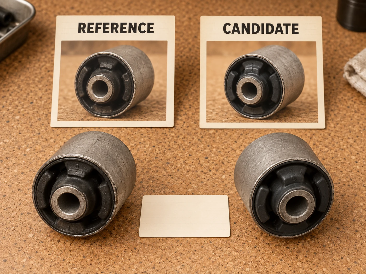
Set a fixed photo convention before reviewing several samples: label the vehicle side, identify the arm face, use the same camera direction and include one overall arm image plus radial and axial detail views. Put the reference and candidate images side by side with their part numbers and dates. A beautiful close-up without a view label can be more confusing than a simple well-indexed photo. If the reference part is mirrored, identify the mirror relationship explicitly rather than mentally rotating one picture.
Record what matches and what remains uncertain. For example, an apparent void pattern may align in the front view while the opposite face has a different molded feature; request the maker’s drawing before approval. A mark may have changed because the bushing supplier revised its design; ask for the revision and the approved equivalence note. A candidate may have the same arm geometry but a different axial sleeve position. Each difference needs a specific disposition rather than a blanket “looks okay.”
Keep the comparison focused on orientation and seating. Verify fitment and package contents in their own records, but do not allow those checks to substitute for this one. An arm can match the vehicle interface and arrive with every advertised component while its directional bushing is incorrectly clocked. Conversely, a correctly oriented bushing does not prove the ball joint, arm geometry or fasteners are suitable. The sample approval sheet should carry separate sign-off fields for each question.
Make an inspection sheet that can be repeated
| Check | Evidence to collect | Approval question |
|---|---|---|
| Part identity | Supplier SKU, side, bushing revision and label | Is this the exact offered assembly? |
| Datum | Drawing revision and named viewing face | Are both samples viewed from the same reference? |
| Radial feature | Close photo of mark, void or tab | Does it align as the maker specifies? |
| Axial seating | Side view and stated measurement method | Is depth or protrusion within the approved rule? |
| Reference | Approved comparison part and provenance | Is the comparator valid and current? |
| Lot control | Supplier inspection plan and report revision | Can the position be maintained in production? |
Use this as a request framework, not a universal tolerance sheet. An approval should identify who inspected the sample, the exact document used and how any differences were resolved. If a supplier returns only a photo with a checkmark, ask for the drawing and view designation behind it. If a mark is absent or ambiguous, record “pending clarification” and request the maker’s instruction. Raising the issue before a large order is less disruptive than trying to reconstruct the correct orientation after several cartons have been distributed.
At incoming inspection, compare a sample from the new lot with the approved reference using the same views. Check that the label and drawing revision still agree. If there is a documented supplier change, confirm whether sample reapproval is needed. The goal is not to measure every arm by an invented rule; it is to preserve the agreed, part-specific orientation evidence across purchasing, production and receiving.
Buyer questions
Can I copy the orientation from the opposite-side arm?
Only if the supplier or vehicle maker’s instruction tells you how to handle the mirrored geometry. MOOG warns that the opposite side can mislead because of mirror effects and limited visibility. Use a named viewing face and the correct left/right drawing rather than assuming visual symmetry.
Does a symmetric-looking bushing need an orientation check?
Ask the maker. A bushing may look symmetric from one side while having internal voids or a hidden mark; another design may have no directional requirement. The exact part document determines whether radial clocking is controlled. Axial seating can still require verification.
Is a photo enough to approve press depth?
A photo shows gross position and damage, but a controlled depth or protrusion requirement needs a defined datum, method and tolerance. Request the drawing and an inspection result when axial seating is critical. Do not declare compliance from an angled photo alone.
Next step: request a marked sample record
Review the current MAKEXCAR Control Arms category, then send a sourcing inquiry with vehicle, market, build range, axle, side, OE reference and proposed SKU. Ask for the bushing and arm drawing revisions, radial mark definition, axial seating rule, clearly labelled reference and candidate photographs, and the supplier’s production inspection plan. Approve the sample only when the exact part’s evidence makes both orientation and seating repeatable.